
Universal Valve Guide puller Remover & Installer set – mechanical type 16pc box
| Manufacturer | TOKAR |
|---|

_kit_profi_33_pcs._in_example_wood.jpg)
_kit_profi_33_pcs_wood.jpg)

Universal Valve Guide Puller / Remover & Installer Set – Mechanical Type, 16 pcs
Compact mechanical tool set for removal and installation of valve guide bushings in cylinder heads using controlled axial force.
Designed for press-fit (interference fit) components where impact loading must be minimized.
Application:
Used for valve guide replacement in automotive and motorcycle engines.
Optimized for common guide sizes with a reduced set of components.
What it actually does:
The tool converts applied torque into axial force via a threaded mechanism, enabling controlled pulling or pressing of the valve guide.
This reduces peak stress compared to impact methods and lowers the risk of bore distortion or cylinder head damage.
- Controlled extraction (pulling mode)
- Controlled installation (pressing mode)
- Minimal shock loading
- Axial force aligned with guide axis
Mechanical principle:
Valve guides are installed with an interference fit in the cylinder head bore.
- Typical interference: 0.02–0.05 mm
- High contact pressure generates significant friction
- Additional resistance may occur due to corrosion and galling (cold welding)
Threaded force generation includes friction losses:
- Torque → axial force via thread pitch
- Thread efficiency typically 30–50%
- Without lubrication, effective force may decrease significantly
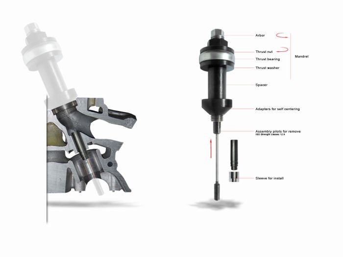
Force is transmitted through mandrel, pilots and adapters, maintaining alignment and reducing bending loads.
Kit structure:
Mandrel assembly:
- Arbor
- Thrust nut
- Thrust washer
- Thrust bearing
Self-centering seat adapters:
- Ø 33, 35, 45 mm
Removal / installation pilots (ISO strength class 12.9):
- Ø 7, 8, 9 mm
Spacers:
- L = 15, 30, 50 mm
Installation sleeves:
- Ø 7, 8, 9 mm
Force required to remove valve guide:
| Condition | Force | kN |
|---|---|---|
| Normal fit | 1–2 tons | 10–20 kN |
| Light seizing | 2–5 tons | 20–50 kN |
| Heavy seizing / galling | 5–10+ tons | 50–100+ kN |
Actual achievable force depends on thread condition, lubrication and friction losses.
Load limits of puller studs (ISO 12.9):
| Thread | Force (kg) | kN |
|---|---|---|
| M5 | 1563 | 15.33 |
| M6 | 2213 | 21.69 |
| M7 | 3181 | 31.24 |
| M8 | 4030 | 39.52 |
| M9 | 5020 | 49.28 |
| M10 | 6388 | 62.65 |
Mandrel capacity:
| Thread | Force (kg) | kN |
|---|---|---|
| M20 | 11990 | 117.68 |
Important recommendations:
- Mandatory: lubricate threads (MoS₂ or graphite grease)
- Dry threads reduce force efficiency and increase wear
- Studs act as overload protection
- Apply force gradually and monitor resistance
- For seized guides:
- Heat cylinder head to 100–150 °C
- Cool guide if possible
- A light initial shock may be used to break stiction
- If resistance increases sharply → stop operation
- Do not apply excessive force or leverage
- If removal fails:
- Drilling out the guide
- Using hydraulic press
In practice:
This compact set covers common valve guide sizes and standard repair operations.
For severe seizure or corrosion, additional thermal or mechanical methods may be required.
Specification:
- Tool type: Valve guide puller & installer set
- Operation: Mechanical (threaded force)
- Set size: 16 pcs
- Coating: Anti-corrosion
- Storage: Plastic box
Working principle:
- Torque → axial force conversion
- Thread-driven pressing / pulling
- Efficiency depends on lubrication
- Alignment via pilots and adapters
Capabilities:
- Removal and installation of press-fit valve guides
- Compact set for common sizes
- Self-centering operation
Advantages:
- Reduced shock loading
- Better control vs hammering
- Lower risk of cylinder head damage
Limitations:
- Limited size range compared to full sets
- Force limited by thread friction and stud strength
- May require heating for seized guides
Use for:
- Cylinder head repair
- Valve guide replacement
- Engine rebuilding